

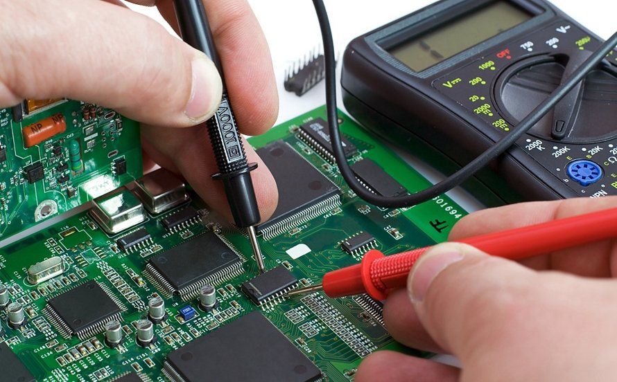
You’ve just finished assembling a custom PCB for an IoT sensor node or a compact AI edge device. You connect power, expecting status LEDs to blink or data to flow, but instead you get silence — or worse, a component begins to overheat. This scenario plays out daily in workshops and startup labs around the world. Learning to test your PCB with a multimeter transforms these moments from guesswork into fast, data-driven troubleshooting that protects both your time and your components.
In the current era of connected devices and intelligent hardware, even small PCB defects can derail entire projects. A single open trace or unintended short can prevent firmware from running, waste days of debugging, and drive up development costs. PCB testing with a multimeter delivers immediate feedback that lets you validate boards before you invest heavily in software integration or field trials. Whether you are iterating on a personal maker project or preparing hardware for a client demo, consistent testing habits separate successful prototypes from repeated failures.
Why Thorough PCB Testing Matters in Modern Hardware Development
Multimeter testing catches the defects most common in hobbyist and small-batch work: broken traces, solder bridges, incorrect voltages, and high-resistance connections. These issues frequently arise from etching problems, cold solder joints, or component placement errors. For IoT gadgets, drone controllers, and AI hardware prototypes that carry microcontrollers, wireless modules, and sensors, catching faults early prevents damage to expensive parts and keeps development momentum alive.
The same electrical integrity principles used in professional manufacturing apply directly to prototype and low-volume builds. By adopting a methodical routine, you improve board reliability while sharpening diagnostic skills that serve every future project. Skipping these checks often leads to the familiar cycle of “it worked on the bench but failed once enclosed.”
Getting Familiar with Your Multimeter’s Key Functions for PCB Work
A digital multimeter combines four essential modes into one affordable instrument. Continuity mode beeps when it detects a low-resistance path, instantly confirming that traces or nets connect properly. DC voltage mode verifies that regulators and power rails deliver the exact levels your components require. Resistance mode quantifies trace health and passive component values, while diode mode checks one-way conduction in protection circuits and LEDs.
These functions rest on basic electrical principles. Continuity identifies near-zero resistance paths, voltage reveals potential differences, and resistance applies Ohm’s law to expose weak spots. Probes must contact clean metal surfaces; dirty tips produce misleading results. Auto-ranging models simplify operation for beginners by selecting the correct scale automatically. Practice first on a known-good board so you internalize normal readings before tackling problematic prototypes.
 Preparation: Setting Yourself Up for Accurate Results
 Preparation: Setting Yourself Up for Accurate Results
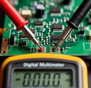
Always remove power from the board and discharge capacitors before probing. This single step protects both you and your meter. Work on a static-safe surface with clean, insulated probes. Wipe flux residue from pads and traces using isopropyl alcohol so contact points are clearly visible and reliable.
Begin with a careful visual inspection. Look for lifted pads, solder bridges, missing components, or physical damage to traces. Fresh batteries in your multimeter guarantee stable readings throughout the session. These few minutes of preparation dramatically improve both safety and efficiency.
Step-by-Step PCB Testing Process
A logical sequence minimizes missed issues and prevents damage. Perform continuity and resistance checks on the unpowered board first. Only apply power for voltage measurements, and always use a current-limited supply. Keep this quick-reference table beside you while testing:
| Testing Mode | What It Checks | Healthy PCB Reading | Abnormal Reading Means | Pro Tip |
| Continuity | Electrical connections between nets | Clear beep or resistance under a few ohms | No beep: open trace, bad via, or poor solder joint | Probe both sides of vias; gently flex the board to find intermittent faults |
| DC Voltage | Power rail and regulator levels | Matches schematic (typically 3.3 V or 5 V) | Wrong voltage: regulator failure, drop, or short | Measure at multiple points along each rail with current-limited supply |
| Resistance | Trace integrity and component values | Near 0 Ω for traces; within tolerance for resistors | Higher than expected: corrosion or weak joints | Power off completely; lift one lead when possible for accuracy |
| Diode Test | One-way conduction in diodes/LEDs/protection | ~0.6–0.7 V forward for silicon | 0 V both ways or OL: damaged component | Excellent for quick in-circuit junction checks |
Start continuity testing on PCB by selecting the sound-wave or diode symbol. Touch one probe to a starting point and the other to the expected destination. A steady beep confirms a solid path; silence tells you to investigate further. This technique quickly reveals etching errors or misaligned vias on both home-made and professional boards.
When measuring voltage on PCB, connect the board to a current-limited supply for safety. Set the meter to DC volts and begin on a higher range. Place the black probe on a solid ground and touch the red probe to each power rail. Readings should match your design values. Inconsistent or low voltages often signal upstream resistance problems or failing regulators.
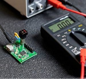 Resistance checks on the powered-off board verify trace quality and component accuracy. Use the lowest ohms range for traces and expect readings close to zero. Higher values point to corrosion, narrow traces, or cold joints. When checking resistors, compare results to schematic values within tolerance. Lifting one lead often improves accuracy when parallel paths exist.
Common Mistakes and How to Avoid Them
The most frequent error is probing a live board without discharging capacitors, which can damage both the meter and the board. Dirty probe tips also cause flaky continuity readings. When voltage is absent, systematically trace from the supply through fuses and upstream traces rather than guessing at a single fault.
Shorts appear as zero resistance between nets that should remain isolated. Inspect carefully for solder bridges and correct them by reflowing or scraping away excess. Intermittent problems may surface only when you tap or apply gentle heat while probing. Document every measurement — patterns emerge quickly and speed future troubleshooting.
Best Practices That Professionalize Your Workflow
Follow a repeatable checklist: visual inspection, continuity, resistance, then powered voltage tests. Perform checks at room temperature because heat affects readings. Verify your multimeter periodically against known references. After electrical testing, run functional power-on tests to confirm the complete system behaves correctly.
High-quality soldering from the start reduces later defects. Once testing finishes, store boards in anti-static packaging. These disciplined habits bring your PCB testing process closer to professional standards and help ensure the hardware foundation of your IoT, embedded, or AI projects remains dependable through multiple iterations.
Conclusion
Effective PCB testing with a multimeter turns uncertain prototypes into reliable hardware you can trust. By combining visual checks with continuity, resistance, and voltage measurements, you catch defects early and build boards that support stable firmware and AI workloads. The time invested in these techniques pays dividends across every project. Consistent practice builds speed, accuracy, and the confidence to tackle increasingly ambitious hardware designs. The more you test PCB with multimeter during development, the quicker these checks become second nature and the more reliable your final products will be.
