

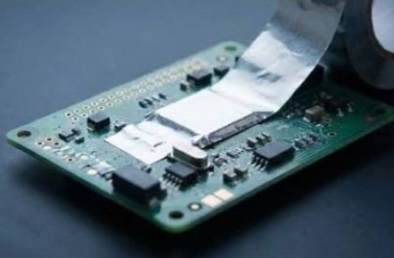
A PCB shield should be part of the board design conversation before component placement becomes fixed. Waiting until a prototype shows interference can leave little room for a frame, grounding features, or service access. Board level EMI shielding works best as a planned element of the assembly, with electrical and mechanical teams agreeing on what must be isolated and how the shield will fit.
Begin by identifying the circuits that need separation. A switching power section, sensitive receiver, and high-speed digital block do not necessarily need the same enclosure treatment. Map the suspected noise sources and vulnerable circuits, then decide where localized shielding could help. This exercise also encourages better placement and routing decisions instead of treating a metal cover as the only remedy.
Consider the shield’s footprint before choosing its shape. Reserve space for the attachment interface, nearby components, and assembly equipment. When a standard outline conflicts with the layout, custom board level shielding can accommodate application-specific geometries. Customization should solve a defined constraint, such as limited height or multiple circuit zones, rather than introduce complexity without a clear manufacturing or performance benefit.
Access requirements determine whether a removable lid is useful. A one-piece shield may suit an assembly that does not need routine access beneath it. A frame with a separate cover allows inspection, adjustment, and component replacement without removing the entire frame. Decide which activities must remain possible after assembly, including debugging, production testing, and servicing.
Height needs careful coordination. Include the tallest component, its tolerance, board variation, and any material positioned beneath the cover. A shield that fits the nominal model may interfere with hardware at the limits of the dimensional stack. Review nearby connectors and the outer housing too. The board level shield is only one part of a larger mechanical assembly. Check clearances during lid removal too.
The electrical interface deserves its own review. Ground connections, attachment geometry, and openings influence how the shield performs in the completed design. Bring the PCB designer and manufacturing team into that discussion early. Ask where discontinuities could remain after soldering, how the interface will be inspected, and whether trace routing beneath or near the frame creates additional constraints.
Heat cannot be considered separately from the cover. Enclosing a warm component changes its surroundings, so evaluate the intended thermal path alongside RF performance. A suitable thermal interface material may connect a component to a metal surface, but its thickness and compression must be coordinated. Ventilation openings also require assessment rather than being added automatically after thermal testing.
3G Shielding Specialties provides standard and custom board shielding in one-piece, removable cover, and multi-zone configurations. Its application engineering services support customers working through shield design requirements. For a productive discussion, supply the board outline, component heights, attachment preferences, access needs, and production plans. Those inputs establish a more useful brief than a request for a generic shielding can.
Use prototypes to evaluate assembly as well as interference. Check placement accuracy, lid installation, component clearance, and accessibility with the actual tools technicians will use. Where several circuits share one cover, verify the intended isolation between sections. Record results for representative operating modes instead of assuming that a quiet idle condition demonstrates performance during demanding workloads. Include prototype and production assembly teams.
Finally, plan the transition to production. Agree on drawings, revision control, packaging, inspection points, and acceptable dimensional variation. Changes to the PCB, cover, or thermal materials should trigger a coordinated review. A well-integrated PCB shield is not merely a piece of metal above the components; it is a repeatable assembly whose electrical, mechanical, and service requirements have been considered together.
