


It is a scenario that has baffled countless junior mechanical engineers and maintenance technicians alike. You design a high-speed centrifugal pump or a heavy-duty electric motor. You press the bearings onto the shaft with textbook precision. You run the machine on the test bench at an ambient temperature of 20°C (68°F), and it purrs like a kitten. The vibration analysis is flawless.
The unit is shipped to the field, installed, and powered up. Two hours later, under a full operational load, the machine emits a violent screech, the motor trips the thermal overload breaker, and the entire system locks up solid.
You tear down the machine, expecting to find a lubrication failure or a misalignment. Instead, you find the bearings completely seized, the steel balls welded to the raceways. What happened?
The machine was destroyed by the “Thermal Ghost”—a fundamental failure to account for thermal expansion and the microscopic gap known as Radial Internal Clearance (RIC). In the pursuit of the “perfect, tight fit,” the engineer ignored the laws of thermodynamics. Let’s dissect the physics of thermal gradients and why understanding internal bearing clearance is the most critical, yet frequently overlooked, aspect of mechanical design.
The Invisible Dimension: Radial Internal Clearance
When novice engineers specify a bearing, they typically focus on three visible dimensions: the bore (inner diameter), the outer diameter, and the width. They ensure the bearing fits the shaft and the housing perfectly.
However, there is a fourth dimension, one that you cannot easily see with the naked eye, but one that dictates the survival of the machine: the Radial Internal Clearance.
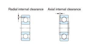
RIC is the total distance that one bearing ring can be displaced relative to the other in the radial direction. In layman’s terms, it is the intentional “slop” or “play” built into the bearing at the factory.
Why build slop into a precision component? Because a bearing does not operate at room temperature. When a machine runs, friction and electrical inefficiencies generate heat. According to the coefficient of thermal expansion, steel physically grows as it gets hotter. If you build a bearing to be perfectly tight at room temperature, it will physically crush its own rolling elements the moment it reaches operational temperature. The intentional gap is there to be consumed by heat.
Decoding the Micro-Gap: The C-Class System
To control this expansion, bearing manufacturers produce bearings with varying degrees of internal clearance. If you look at the suffix of a bearing part number, you will often see a designation like C3 or C4.
To prevent catastrophic thermal lockup, engineers must possess a fluent understanding of the differences between C0, C3, and C4 clearances.
Here is the engineering logic behind the codes:
- C0 (Normal Clearance): Often omitted from the part number (if there is no C-suffix, it is C0 by default). This is for standard applications operating at room temperature with minimal heat generation, where the shaft and the housing remain at roughly the same temperature.
- C3 (Greater than Normal): The industry standard for electric motors and equipment subject to moderate thermal gradients. The extra microns of space allow the inner ring to expand without creating a pre-load condition.
- C4 (Greater than C3): Used in severe thermal environments, such as induced draft fans, exhaust blowers, and high-temperature vibratory screens. At room temperature, a C4 bearing feels alarmingly loose—but at 150°C, it becomes perfectly dimensionally stable.

The Physics of the Thermal Gradient
Why does the clearance disappear in the first place? To understand this, we must look at the thermal gradient—the difference in temperature between the inner ring and the outer ring.
In almost all industrial applications (like an electric motor or a gearbox), the heat is generated at the shaft. The inner ring of the bearing is pressed tightly onto this hot shaft, meaning the inner ring absorbs the heat directly.
Conversely, the outer ring is seated in a massive cast-iron or aluminum housing. This massive housing acts as a giant heat sink, constantly radiating heat away into the surrounding air.
The Result: The inner ring gets much hotter than the outer ring. Because it is hotter, the inner ring expands outward at a faster rate than the outer ring expands. As the inner ring swells, it pushes the steel balls outward, rapidly consuming the Radial Internal Clearance. If the initial clearance (say, a C0) was too small to accommodate this specific temperature differential, the gap drops to less than zero.
The bearing is now in a state of severe “negative clearance” or uncontrolled preload. The balls are violently wedged between the raceways, the lubricating oil film is instantly pierced, and the bearing self-destructs in a matter of minutes.
The Mechanical Trap: Interference Fits
Heat is not the only force actively trying to destroy the internal clearance. The mechanical installation process itself consumes a massive portion of the gap before the machine even turns on.
To prevent the bearing from slipping on the shaft, engineers design an “interference fit” (a tight press fit). When you force a 50mm inner ring onto a 50.015mm shaft, the steel of the inner ring is physically stretched. This mechanical stretching forces the raceway outward, consuming up to 50% of the bearing’s factory internal clearance.
If you use a standard C0 bearing, the interference fit alone might consume most of your safety gap. Add a moderate thermal gradient once the machine starts up, and you have a guaranteed recipe for seizure. This is why C3 is the absolute minimum requirement for any bearing undergoing a heavy press fit on a high-speed shaft.
The Human Factor: The “Slop” Fallacy
Perhaps the biggest threat to proper bearing clearance isn’t the math; it’s human psychology on the shop floor.
A well-meaning maintenance mechanic pulls a C4 bearing out of the box to install it on a hot exhaust fan. They hold the inner ring, wiggle the outer ring, and hear a distinct rattle. Their mechanical intuition tells them, “This bearing is defective; it has too much slop.” Believing they are saving the company from a breakdown, they walk back to the tool crib, throw the C4 bearing away, and replace it with a standard C0 bearing that feels “nice and tight.”
By acting on intuition instead of engineering logic, the mechanic has just inadvertently planted a mechanical time bomb. Educating the maintenance staff that “loose is necessary” is one of the most difficult but vital cultural shifts in a manufacturing plant.

The Blueprint for Survival: Systematizing Selection
The Sealing Paradox, the Oval Trap, and the Thermal Ghost all point to a singular, undeniable truth: modern rotating equipment operates on the bleeding edge of physics. The days of simply picking a part number out of a catalog based purely on the shaft diameter are over.
True mechanical reliability requires a deductive, systemic approach. Engineers must calculate the thermal gradient, factor in the loss of clearance from the interference fit, determine the dynamic shock load, and specify the exact sealing architecture.
To prevent these invisible variables from causing catastrophic downtime, design teams and procurement officers must standardize their specification protocols. Rather than guessing, professionals should comprehensively read this selection guide provided by specialized manufacturers. Utilizing a structured selection matrix ensures that thermal expansion, mechanical fitment, and load requirements are mathematically accounted for before the purchase order is ever written.
Conclusion: Respect the Gap
The next time you design a rotating assembly or troubleshoot a premature failure, look beyond the basic dimensions. Look for the Thermal Ghost.
Remember that a bearing is a dynamic system whose physical dimensions actively change depending on the operating temperature. By understanding the critical physics of thermal gradients, respecting the necessity of C3 and C4 internal clearances, and relying on rigorous, standardized selection guides, you can protect your machinery from self-destruction.
In the world of high-performance mechanics, perfection isn’t about fitting things as tightly as possible. True engineering perfection is knowing exactly how much empty space to leave behind.
Frequently Asked Questions (FAQ)
If a machine runs at a very cold ambient temperature, do I need a different clearance? Yes. In extreme cold environments (such as industrial freezers or aerospace applications), the housing may shrink faster than the shaft, which can also reduce internal clearance. Additionally, standard steel can become brittle at sub-zero temperatures. In these edge cases, engineers must calculate the exact dimensional shrinkage and often specify specialized lubricants and clearances.
Can I manually measure the internal clearance of a bearing before installation? While manufacturers use highly precise pneumatic gauges to measure clearance in microns, a simple field test is not reliable. Wiggling the bearing by hand only provides a subjective “feel” and cannot accurately quantify whether a bearing is C0, C3, or C4. Always trust the laser-etched suffix code on the bearing ring itself rather than the packaging or a manual wiggle test.
What happens if I use a C3 bearing when a C0 was specified? Using a bearing with too much clearance for the application (e.g., using a C3 in a low-speed, room-temperature assembly with a light fit) can result in excessive radial runout. The shaft may vibrate, the bearing will generate more noise, and the rolling elements may “skid” instead of rolling smoothly, which can lead to premature wear of the raceways.


